HowTo: Use periodic meshes and enforce periodic boundary conditions
In order to solve a problem with periodic boundary conditions, the Mesh object should have a
periodic topology. This can be achieved in one of two ways:
- By reading a periodic mesh from disk.
- By identifying periodic vertices (e.g. through a translation vector), and then creating a new periodic mesh.
Reading a periodic mesh from disk
MFEM supports reading periodic meshes from a variety of mesh file
formats. Several periodic sample meshes are included with MFEM in the
data directory:
MFEM format:
periodic-square.mesh: a 3x3 Cartesian mesh of the (periodic) square [-1,1]^2periodic-hexagon.mesh: a quad mesh of a periodic hexagonal domain with 12 elementsperiodic-cube.mesh: a 3x3x3 Cartesian mesh of the (periodic) cube [-1,1]^3
Gmsh format (the corresponding .geo files are also included):
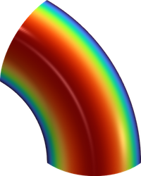
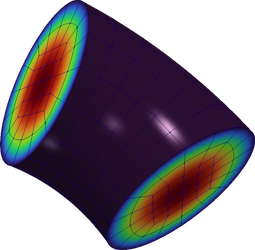
periodic-square.msh: a 4x4 Cartesian mesh of the (periodic) unit squareperiodic-cube.msh: a 4x4x4 Cartesian mesh of the (periodic) unit cubeperiodic-annulus-sector.msh: a 2D mesh of an annular sector with periodic boundaries defined by a rotationperiodic-torus-sector.msh: a 3D mesh of a torus sector with periodic boundaries defined by a rotation
Any of these meshes can be loaded as usual using MFEM (e.g. using the -m flag in the MFEM
examples), and the periodic topology will be automatically handled.
(Note that some periodic boundaries (such as periodic-cube.mesh) contain so-called "internal
boundary elements", which may result in boundary conditions being enforced for some examples.)
| Example 0 on Periodic Annulus | Example 0 on Periodic Torus |
|---|---|
 |
 |
Creating a periodic mesh by identifying vertices
MFEM can also create periodic meshes from non-periodic meshes by identifying periodic vertices. The
function Mesh::MakePeriodic creates a periodic mesh from a non-periodic mesh given such a vertex
identification. For example, if we wish to create a periodic line segment, then we would like to
identify the two endpoints of the line segment since they represent the same point in the periodic
topology. An example of creating this vertex mapping in the case of a line segment is described
here.
It is often more convenient to describe the periodicity constraints in terms of translation
vectors. Any two vertices that are coincident under any of the given translation vectors will be
considered topologically identical. MFEM can generate a vertex mapping from these translation
vectors using the Mesh::CreatePeriodicVertexMapping. An example using this functionality to create
a mesh of the periodic square is shown here.
(Note that periodic meshes use a discontinuous nodal function for mapping the reference space
to the physical one (see Mesh::SetCurvature). The vertex coordinates are no longer meaningful
after calling Mesh::MakePeriodic. You should refrain from accessing them and use the nodal
grid function returned by Mesh::GetNodes or single nodes through Mesh::GetNode instead.)
Example: creating a periodic line segment with a vertex map
Mesh mesh = Mesh::MakeCartesian1D(10);// Make a mesh of the unit interval with 10 elements
// Create the vertex mapping. To begin, create the identity mapping.
std::vector<int> v2v(mesh.GetNV());
for (int i = 0; i < mesh.GetNV(); ++i)
{
   v2v[i] = i;
}
// Modify the mapping so that the last vertex gets mapped to the first vertex.
v2v.back() = 0;
Mesh periodic_mesh = Mesh::MakePeriodic(mesh, v2v); // Create the periodic mesh
Example: creating a periodic square with translation vectors
// Create a 10x10 quad mesh of the unit square;
Mesh mesh = Mesh::MakeCartesian2D(10, 10, Element::QUADRILATERAL);
// Create translation vectors defining the periodicity
Vector x_translation({1.0, 0.0});
Vector y_translation({0.0, 1.0});
std::vector<Vector> translations = {x_translation, y_translation};
// Create the periodic mesh using the vertex mapping defined by the translation vectors
Mesh periodic_mesh = Mesh::MakePeriodic(mesh, mesh.CreatePeriodicVertexMapping(translations));